TIGRE Telescope
Tests before overhauling
Menu:
Update:
16th January 2024
Telescope tests before overhauling
Status (1. 7. 2004):
The telescope was restituted to the Halfmann workshop for overhauling.
Optics:
Wave front aberrations of the mirrors were measured by the manufacturer. The results are given in the tables below.
The sum of all specific aberrations is given in row 1, for example rms=0.032*lambda.
(The testing wavelength was 633nm.)
Specific aberrations (for example, C33) are given in the other rows, by the value
(0.026 in case of C33) which remains after subtracting the specific aberration
from the total one.
Primary mirror (M1)
| RMS | P-V | Comment | ||
|---|---|---|---|---|
| total | 0.032 | 0.226 | to multiply with 633nm | |
| minus | residual aberration | |||
| R | 0.032 | 0.226 | defocus | |
| A | 0.032 | 0.226 | astigmatism | |
| C | 0.032 | 0.226 | coma | |
| C33 | 0.026 | 0.154 | triangular coma | |
| A4 | 0.032 | 0.226 | quadr. astigmatism | |
| S3 | 0.032 | 0.226 | third order spher. aberr. | |
| M | 0.025 | 0.160 | zonal errors |
The M1 aberrations are dominated by triangular coma but the total rms is strongly better than our specification.
Secondary mirror (M2)
| RMS | P-V | Comment | ||
|---|---|---|---|---|
| total | 0.035 | 0.267 | to multiply with 633nm | |
| minus | residual Aberration | |||
| R | 0.035 | 0.267 | Defocus | |
| A | 0.028 | 0.234 | Astigmatism | |
| C | 0.035 | 0.267 | Coma | |
| C33 | 0.031 | 0.234 | Triangular Coma | |
| A4 | 0.035 | 0.268 | quadr. Astigmatism | |
| S3 | 0.035 | 0.267 | Third order spher. aberr. | |
| M | 0.021 | 0.247 | zonal error |
The M2 aberrations are dominated by triangular coma and astigmatism. However, the total rms is much better than
our specification.
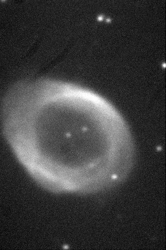 Photo: Ring nebula at Lyra (M57). Exposure 2min.
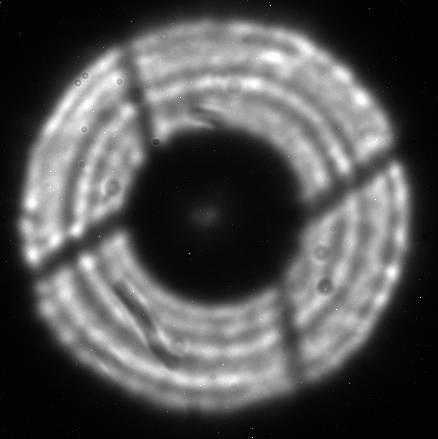
Optical alignment and adjustment:
The two ST7 CCD images below show pupil plates of defocused stellar images (2min exposures).
(see R.N. Wilson, Reflecting Telescope Otics II, p. 135)
 intrafocal
 extrafocal
The dark stripe in the lower left of the extrafocal image and some very small scale structures are caused by dirt.
(There was a long time-delay between the mirror installation and that test.)
However, zonal errors are visible. Their influence on the spot concentration was estimated by
W. Heilemann (Carl Zeiss Jena GmbH) from the number of zones (4), the aperture of 1200mm and the rms of
M1 and M2 (a total of 27.6nm) yielding an approximate light concentration of 80% in 0.35" which is much better
than specified. An exact estimate by help of a Shack-Hartmann test is planned.
Telescope pointing
In order to precisely estimate azimuth and elevation of a telescope pointing, the characteristics of telescope alignment and
adjustment have to be considered (pointing model). These characteristics can be described
by the following parameters:
an: northern deviation of the azimuth axis from the zenith
ae: eastern deviation of the azimuth axis from the zenith
npae: deviation from 90° of the angle between azimuth and elevation axes
bnp: angle between optical axis and tube axis (alignment error)
aoff: angle between azimuth encoder zero and azimuth 0°
eoff: angle between elevation encoder zero and elevation 0°
aes: centering error of the azimuth encoder (sine)
aec: centering error of the azimuth encoder (cosine)
ees: centering error of the elevation encoder (sine)
eec: centering error of the elevation encoder (cosine)
c1-c4: HRT specific harmonics in elevation
c5: HRT specific
Thus the pointing model of HRT is specified by 10 standard parameters plus 5 HRT specific ones:
dE=eoff+an*cos(a)+ae*sin(a)+ees*sin(e)+eec*cos(e)+c5/cos(e)+c1*sin(2*a)+c2*cos(2*a)
+c3*sin(3*a)+c4*cos(3*a)
dA=aoff+an*sin(a)*tan(e)-ae*cos(a)*tan(e)+npae*tan(e)-bnp/cos(e)+aes*sin(a)+aec*cos(a)
The deviations dA,dE between the actual positions in azimuth and elevation and the catalogue positions
(corrected for effects such as atmospheric refraction) were determined for a total
number of 126 stars. The resulting pointing model (see table below) yields residuals with rms=2" in elevation and 5" in azimuth.
These values should be further improvable because of a small hysteresis in azimuth which is not
included in the pointing model but which was eliminated just before
giving back the telescope for overhauling.
The residuals to the pointing model are plotted in the following figures. Note the good pointing up to
elevation 89° (the zenith limit before overhauling):

Telescope Tracking
A good pointing is a necessary requirement for good tracking. At high tracking loss rates (observed at early stages
of HRT - the reasons for it could be eliminated by the manufacturer), the autoguider would
not be able to keep the star
on the fibre. Therefore a maximum loss rate of 0.5"/min was specified. This was achieved and excelled.
The tracking performance was tested at many sky positions up to 89° in elevation. The maximum tracking loss rate
of 0.2"/min was observed at west but in most cases, a value lower than 0.1"/min was observed
including observations close to the zenith.
This is demonstrated with two examples at south and west and near the zenith (see figure, left and right side).
The upper panels show the deviation from the standard (separated in azimuth and elevation)
as a function of time (UT hour). These loss rates are sufficiently low to be safely handled by the autoguider.
After subtracting the trends (lower panels), noise is visible; its standard deviation is correlated
with seeing, at least in azimuth. That means that the tracking (and also guiding) performance of HRT is limited
by the atmospheric conditions.
Tracking tests near the pole yielded a sporadically appearing oscillation in elevation. The amplitude of
that oscillation was strongly variable from below the detection threshold up to 1". The oscillation period is correlated
with the tracking velocity:
C=P*v=0.01°
The constant C matches the encoder cycle (360°/36000 lines), revealing that the encoder signal is source of the oscillation.
However, this problem is not a matter of principle because it was never observed in azimuth although the azimuth
drive resp. encoder is identical in construction with that in elevation. Therefore this (last) error can and will be
solved during HRT overhauling.

Here the probability that the deviation R from the standard position had exceeded a certain value (0.6"
is chosen) is depicted over FWHM of the stellar image. It indicates that the stellar centroid motions
are caused mainly by seeing.
Software tests
The telescope control software TCS was developed by 4PI Systeme GmbH Sonneberg (a subcontractor of
Halfmann Teleskoptechnik).
J.N. Gonzalez Perez (Hamburg Observatory) wrote the software for acquisition, guiding, and focusing.
This and TCS were
tested during 2003-2004 to find and eliminate software bugs. To the end of the test phase, the software
for robotic telescope operations (roboter) was installed and tested. The following parts of the roboter were
developed by the
Astrophysical Institute Potsdam as a part of the
STELLA project:
-
-- Telescope initialising and encoder referencing,
-- setting the telescope in a well-defined status after finishing the program but also
after an error which cannot be handled,
-- logging telescope operations,
-- auto restart after an electrical power fail,
-- auto reset after a loss of the target in consequence of a telescope bug,
-- automatic selection of a target star from a sample of possible objects,
-- telescope pointing,
The following operations of the roboter were developed at Hamburg Observatory:
-- identifying the star on the AGU CCD and centering the star on the fibre,
-- guiding during the spectrograph exposure time (simulated with 10min exposures),
-- auto focusing.
The software controlling the sky monitor was developed and successfully tested by H.J. Hagen (Hamburg Observatory).